Draw a plan — get 3D
Parametric generation of urban and architectural environments from an ordinary 2D drawing. Tag faces and lines — the system assembles a 3D scene from your templates.
Three steps from drawing to 3D
The whole process is three simple steps — no programming, no nodes.
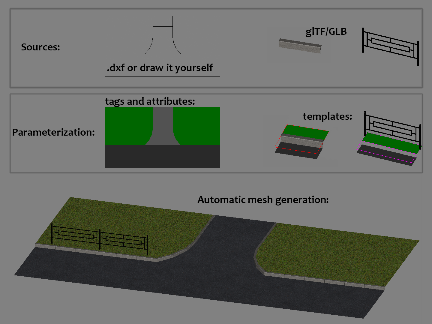
1. Source data. Import a plan from DXF or draw it right in the browser. Complex geometry — curbs, fences, railings — you load as ready-made 3D models (glTF/GLB).
2. Parameterization. Tag faces and lines with your own tags and attributes and assemble templates from your 3D models that get laid along the right edges.
3. Build. Press Build 3D — the system builds the topology, lays out the templates and produces a finished 3D scene with materials.
How it works
Key capabilities
CAD plus declarative rules — no visual programming.
A familiar CAD interface in the browser
Primitives, object snap, layers, user coordinate systems, DXF and glTF/GLB import and export, full Undo/Redo.
Automatic topology
Regions are detected automatically from line intersections — no manual fill contours. Your source objects stay intact: they are never split or merged. Any edit triggers a reactive rebuild in the background.
Declarative tags and classes
Attach your own tags and attributes to faces and edges, and the system picks the matching template on its own. Minimal markup, maximal geometry.
Templates from your own 3D models
You build a template from your own 3D models. Each template is fully configurable — where and in what context it appears, how it repeats and deforms.
Your data stays with you
A project lives entirely in the browser and in a self-contained .asprj file that you export yourself. Nothing is sent to a server — everything stays on your device.
Try it right in your browser
No install, no license keys — it opens from a link. Your projects are stored in your browser.
Community & contacts
Subscribe, ask questions, share your work.